


- Tool: Matek Configurator
- via A or B
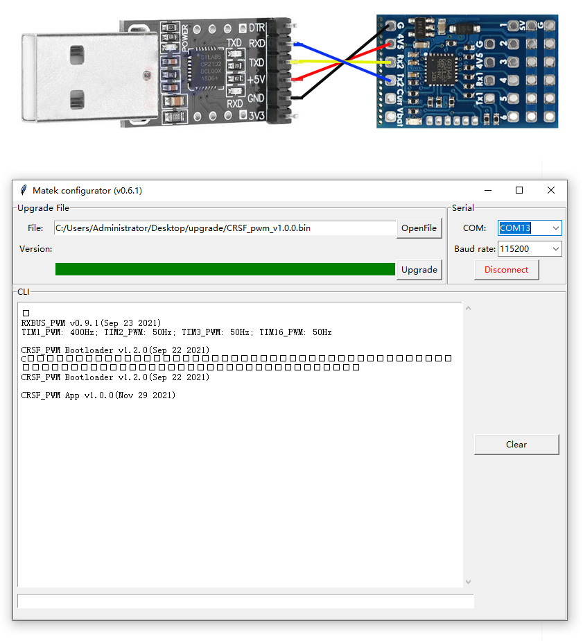
A. USB-TTL modules, such as CP210x, FTDI
1. Wiring
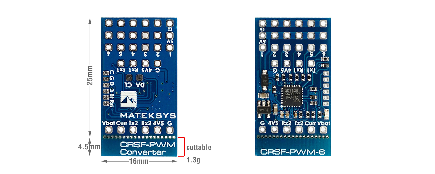
- TX2 — USB-TTL module RX
- RX2 — USB-TTL module TX
- 4v5 — USB-TTL module 5V
- G — USB-TTL module GND
2. Connect USB-TTL module to PC
3. CRSF-PWM board CLI mode will active after powering on for 10 seconds
4. Open Matek configurator, Select COM port of USB-TTL, Baud rate 115200, Click “Connect”
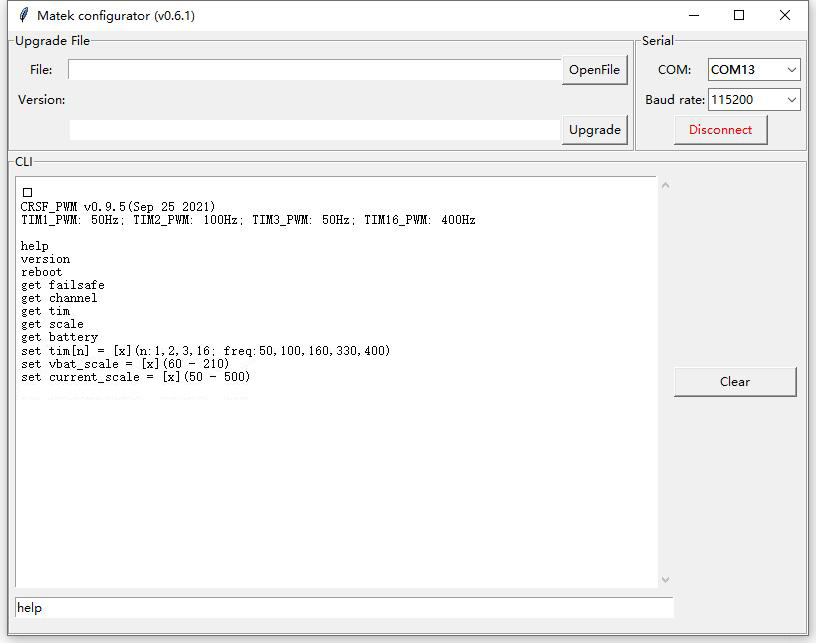
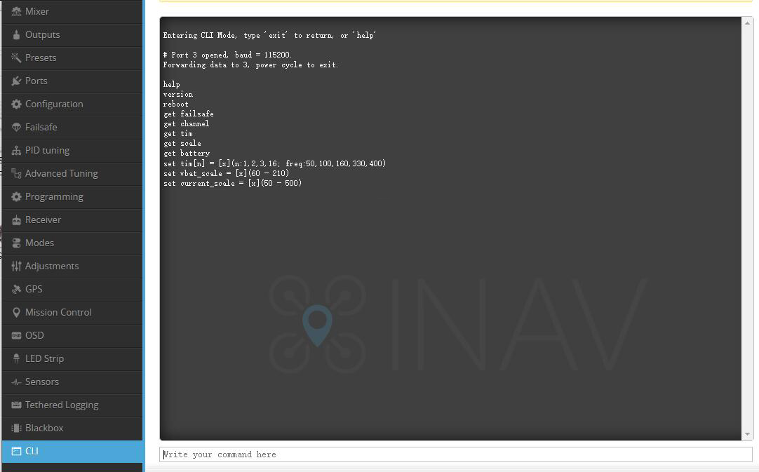
5. Type command “help”
B. INAV/BF serial passthrough
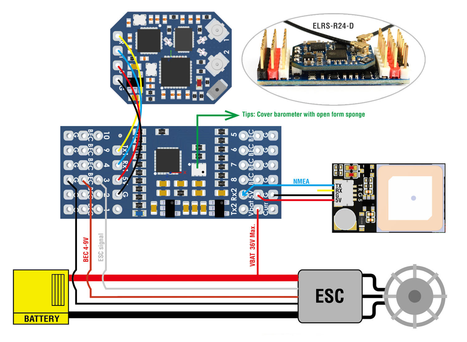
1. Wiring
- TX2 — FC any spare UART_RX
- RX2 — FC any spare UART_TX
- 4v5 — FC 5V or 4V5
- G — FC GND
2. Connect FC USB to PC
3. CRSF-PWM board CLI mode will active after powering on for 10 seconds
4. open INAV/BF configurator, connect FC to configurator
5. click INAV/BF configurator “CLI” tab, type “serialpassthrough x 115200”, x = UART number -1, e.g. CRSF-PWM board connect to FC UART4, type “serialpassthrough 3 115200”.
6. Type command “help”
************************************************************
*************** Type all command with lowercase ***************
************************************************************
help
List all commands
- help
- version
- reboot
- get failsafe
- get channel
- get tim
- get scale
- get battery
- get baro (fw 2.0.0 or newer)
- set tim[n] = [x](n:1,2,3,16; freq:50,100,160,330,400)
- set vbat_scale = [x](60 – 210)
- set current_scale = [x](50 – 500)
- set output_5 = ch[x](11 or 12)
version
list CRSF-PWM firmware version
- CRSF_PWM App v0.9.5(Sep 25 2021)
reboot
restart CRSF-PWM board
- If receiver is connected and bound to transmitter, Failsafe value will be reset according to the transmitter joystick position.
get failsafe
list failsafe value saved
- PWM CH1_failsafe = 1500;
- PWM CH2_failsafe = 1500;
- PWM CH3_failsafe = 988;
- PWM CH4_failsafe = 1500;
- PWM CH5_failsafe = 1000;
- PWM CH6_failsafe = 1000;
- PWM CH7_failsafe = 1000;
- PWM CH8_failsafe = 1000;
- PWM CH9_failsafe = 2000;
- PWM CH10_failsafe = 2000;
get channel
list all channels PWM value according to joystick position if receiver is connected and bound to transmitter
If receiver is not connected or not bound to transmitter, the CH PWM value = failsafe value saved
- CH1 = 1502;
- CH2 = 1500;
- CH3 = 1007;
- CH4 = 1498;
- CH5 = 1000;
- CH6 = 1000;
- CH7 = 1000;
- CH8 = 1000;
- CH9 = 2000;
- CH10 = 2000;
get tim
list PWM frequency on all TIM
- TIM2 = 50Hz (CH1,2,4);
- TIM16 = 50Hz (CH3);
- TIM3 = 50Hz (CH5,6,7,8);
- TIM1 = 50Hz (CH9,10);
set tim[n] = [x](n:1,2,3,16; freq:50,100,160,330,400)
set PWM frequency on each TIM/CH
- “n” range: 1, 2, 3, 16
- “[x]” range: 50, 100, 160, 300, 400
- TIM2: CH1, CH2, CH4
- TIM16: CH3
- TIM3: CH5, CH6, CH7, CH8
- TIM1: CH9, CH10
- 50Hz by default. Compatible with both old school and modern PWM ESC/servos
- Check ESC and servos datasheet to make sure the ESC and servos can work stably at that PWM frequency you will set.
- Usually Analog servos work at 50Hz only, some digital servos can work at 400Hz. ESC supported by oneshot/DShot can work at 400Hz PWM
- e.g. type “set tim16 = 400”, PWM output on CH3 will run at 400Hz
- e.g. type “set tim2 = 100”, PWM output on CH1, CH2,CH4 will run at 100Hz
get scale
- vbat_scale = 110;
- current_scale = 150;
get battery
list Battery voltage and current, Even if there is no current through the shunt resistor, there may be a certain current reading due to the offset and tolerance of current sensor.
- voltage = 0(mV);
- current = 0(mA);
get baro (fw 2.0.0 or newer)
list barometer altitude and temperature, support MS5611 (I2C address 0x77) and SPL06-001 (I2C address 0x76)
- SPL06: alti = 10(cm), temp = 20(C);
set vbat_scale = [x](60 – 210)
- 1K:10K resistor: 110 by default
- Because of components tolerance you can adjust this to match with multimeter readout.
set current_scale = [x](50 – 500)
- current_scale = 150 by default
- If current readout 10A on telemetry, 10.8A on current meter, you can set the scale to (10.8/10)*150=162
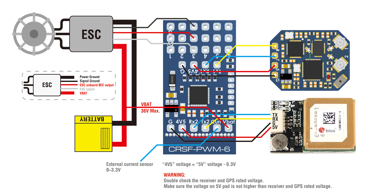
- For using external current sensor on CRSF-PWM-6, You can adjust this value to match with the scale of external current sensor.
set output_5 = ch[x] (range to 1-16)
- with this CLI command, You can remap other PWM channel signal to output_5 pin of CRSF-PWM board.
- e.g. “set output_5 = ch11”, ELRS receiver will output PWM 11 signal on pin No.5 of CRSF-PWM