


Product Detail
Product Parameter
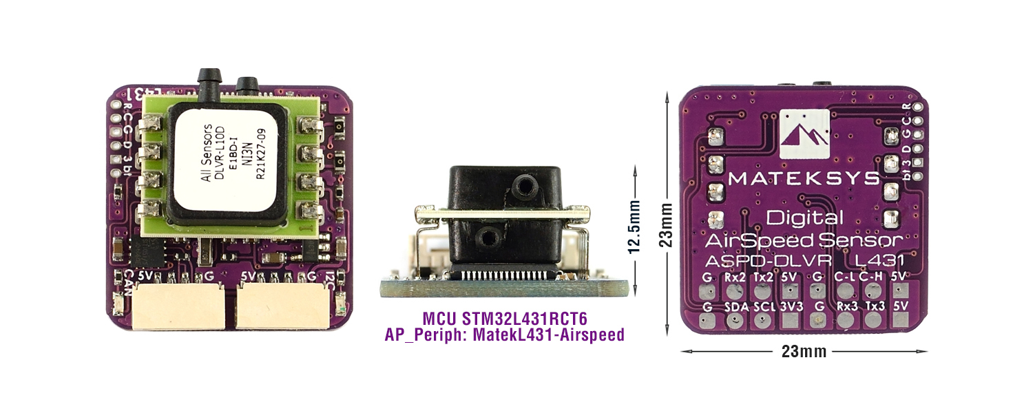
As STM32F303CCT6 and STM32F405RGT6 are in shortage. ASPD-DLVR has been updated with L431 CAN node since Mar.2022. L431 version has identical PCB size(purple PCB) and layout to previous F405 version.
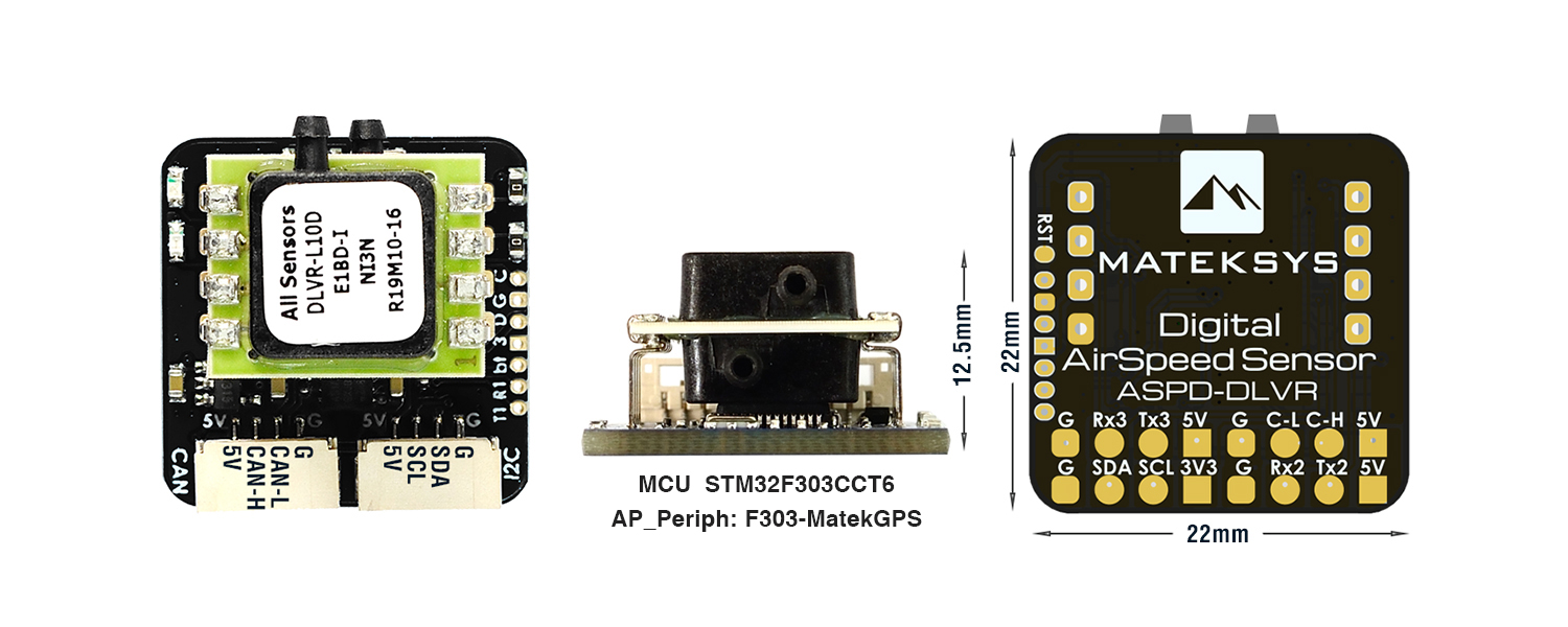
- Black PCB, F303 CAN node, Jul.2020 — Dec.2020
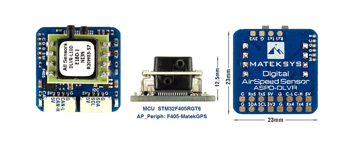
- Blue PCB, F405 CAN node, Jan.2021 — Feb.2022
- Purple PCB, L431 CAN node, Mar.2022 — now
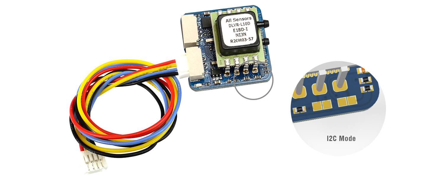
Digital AirSpeed sensor ASPD-DLVR
Update
As STM32F303CCT6 and STM32F405RGT6 are in shortage. ASPD-DLVR has been updated with L431 CAN node since Mar.2022. L431 version has identical PCB size(purple PCB) and layout to previous F405 version.
- Black PCB, F303 CAN node, Jul.2020 — Dec.2020
- Blue PCB, F405 CAN node, Jan.2021 — Feb.2022
- Purple PCB, L431 CAN node, Mar.2022 — now
Gallery
Spec.& Settings
Specifications & Features
- ArduPilot AP_Periph L431/F405/F303 CAN node
- All sensors DLVR-L10D, Industrial temperature range
- CAN & I2C Interface
- Typical Platforms: Fixed-Wing, QuadPlane, VTOL
- CAN JST-GH connector, DroneCAN Protocol
- I2C JST-GH connector, DLVR-L10D I2C mode (I2C address 0x28)
- F303 ver. (Black PCB)
- UART1, Firmware update
- UART2, Spare for external GPS
- F405 ver. (Blue PCB)
- UART1, Firmware update
- UART4, Spare for external GPS
- L431 ver. (Purple PCB)
- UART2, Firmware update
- UART3, Spare for external GPS
- CAN bootloader LED, Blue
- Fast blinking, AP_Periph bootloader
- Slow blinking, CAN Node ready
- 3.3V Power LED, Red
- Input voltage range: 4.5~5.5V
- Power consumption: 60mA
- Operating Temperatures: -20°C to 85°C
- Pressure Range: 2500Pa (± 10 inH2O)
- Burst Pressure: 75kPa
- Speed Range: 227 km/h
- 22mm*22mm*12.5mm(F303 ver.)
- 23mm*23mm*12.5mm(F405 ver.)
- 4g
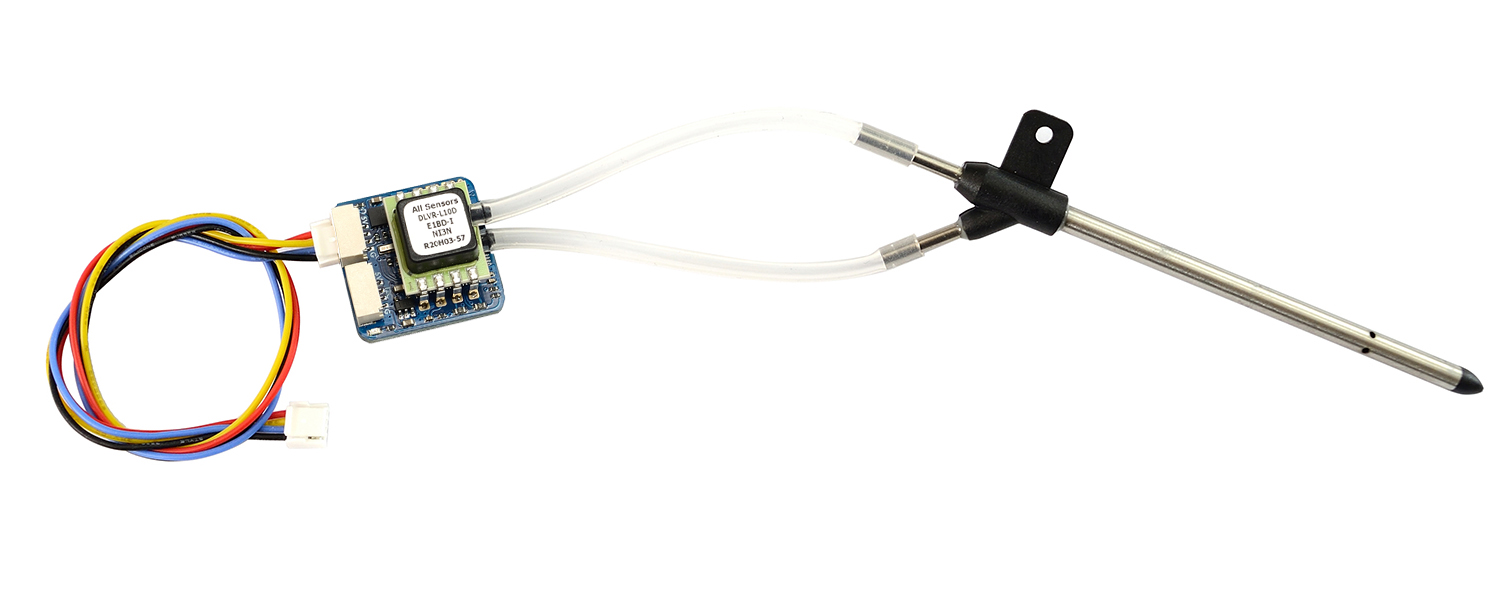
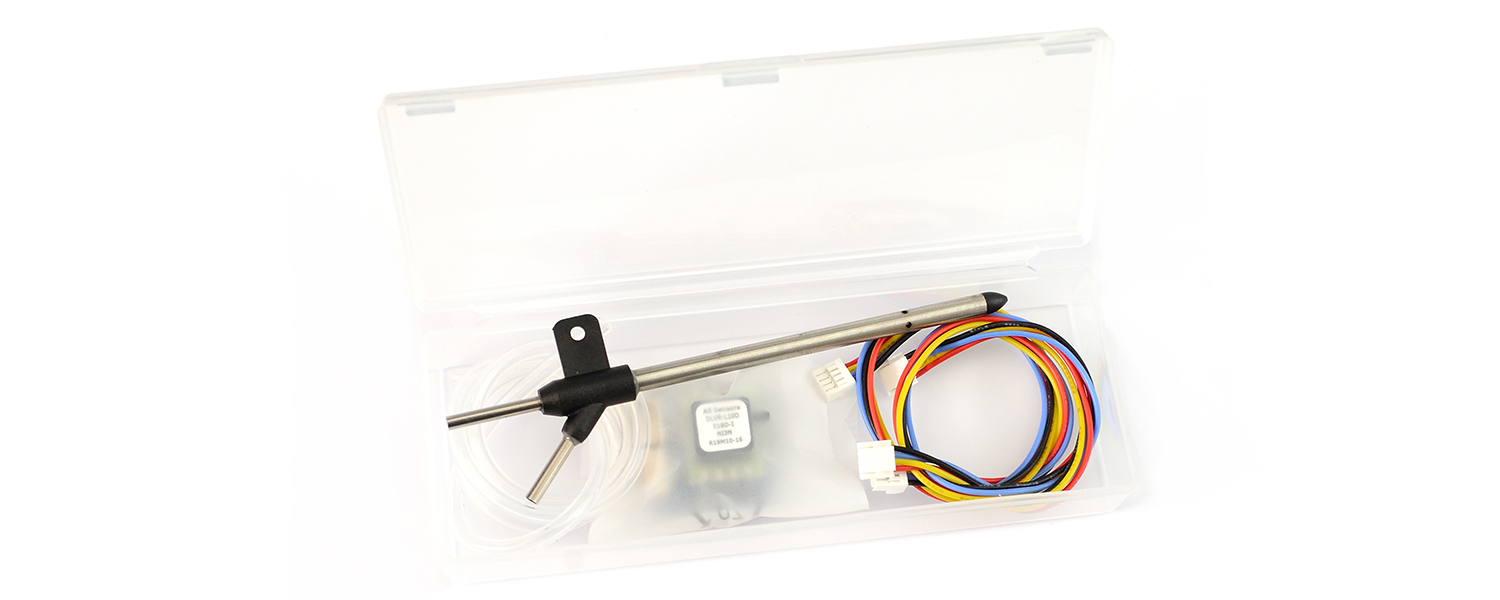
Includes
- 1x ASPD-DLVR
- 2x JST-GH-4P to JST-GH-4P 20cm silicon wire
- Pitot Tube
- Clear silicon tubing 40cm
AP_Periph & DroneCAN protocol
- Firmware AP_Periph https://github.com/ArduPilot/ardupilot/blob/master/Tools/AP_Periph/README.md
- DroneCAN protocol https://dronecan.github.io/
Tips
- ArduPilot has removed DLVR I2C support by default on flight controller with 1MB flash MCU(such as F405, F745 series).
——————————————————————————-
Wiring and AP Parameters
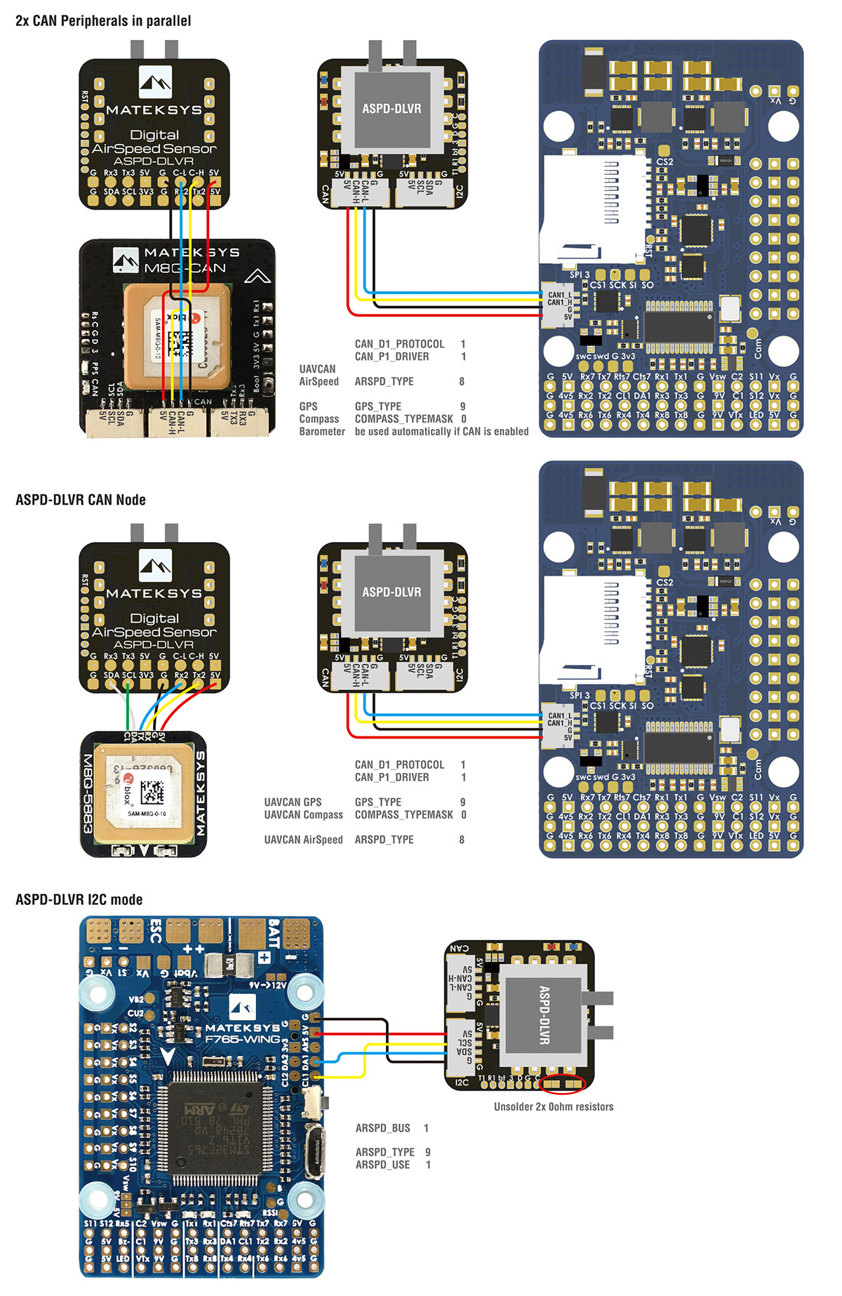
| CAN | or | I2C | ||
| ASPD-DLVR | Flight Controller | ASPD-DLVR | Flight Controller | |
| 5V | 5V | 5V | 5V | |
| C-H | CAN High | SCL | SCL | |
| C-L | CAN Low | SDA | SDA | |
| G | GND | G | GND | |
| CAN_D1_PROTOCOL | 1 | |||
| CAN_P1_DRIVER | 1 | ARSPD_PIN | 65 | |
| ARSPD_TYPE | 8 (UAVCAN) | ARSPD_TYPE | 9 (I2C-DLVR-10in) | |
| ARSPD_USE | 1 | ARSPD_USE | 1 | |
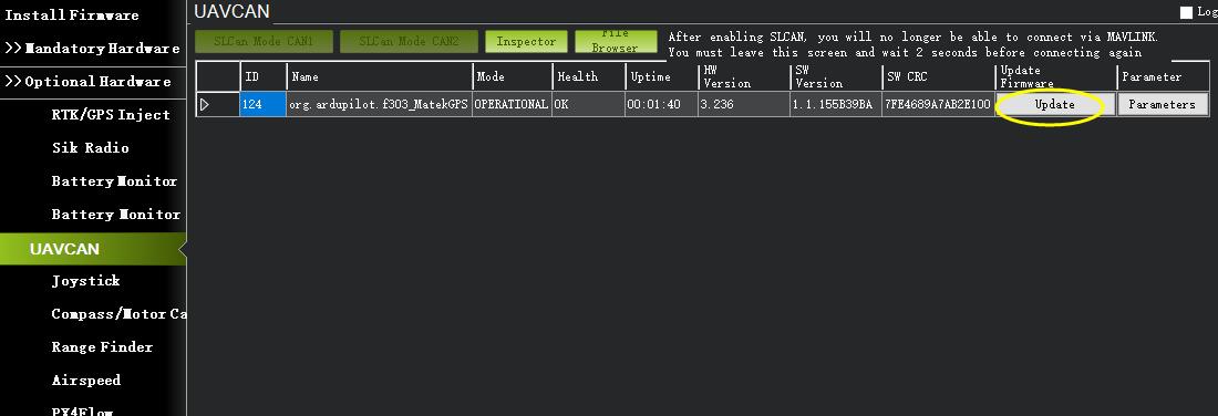
| Mission Planner-> Initial Setup-> Optional Hardware-> UAVCAN-> MAVlink CANx -> Parameters -> ARSPD_TYPE |
9 (DLVR-10in)
Write and reboot |
|||
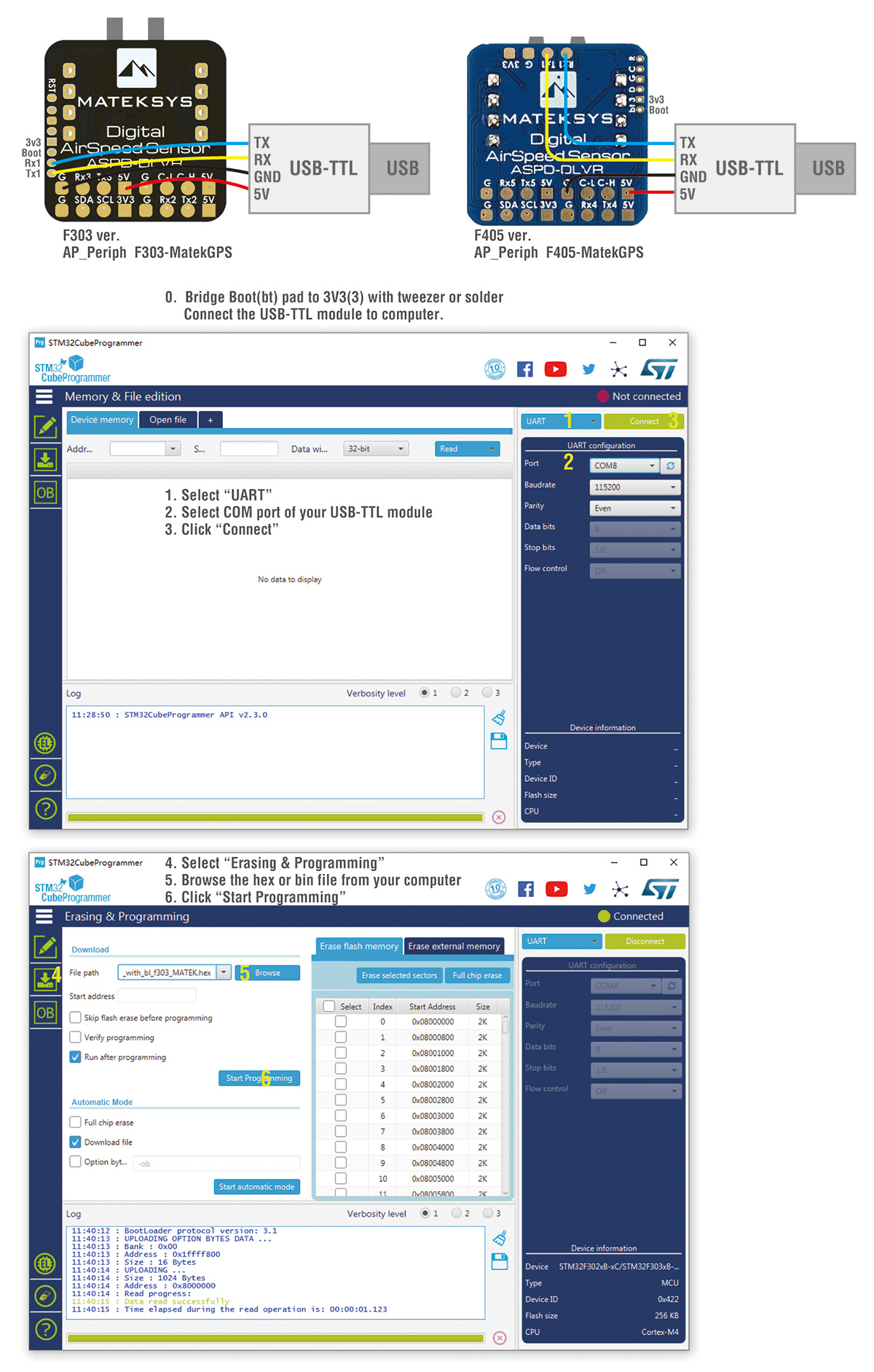
Pinout & Pads
| GH-4P Pin | Signal | Wires color | GH-4P Pin | Signal | Wires color | |
| 5V | 4~6V input | Red | 5V | 4.5~5.5V input | Red | |
| C-H | CAN high | Yellow | SCL | I2C-SCL | Yellow | |
| C-L | CAN low | Blue | SDA | I2C-SDA | Blue | |
| G | GND | Black | G | GND | Black |
| T1 | UART1-TX | Tx1 | UART1-TX | bt | Boot pin | ||
| R1 | UART1-RX | Rx1 | UART1-RX | 3 / 3v3 | onboard LDO output | ||
| Tx2 | UART2-TX | Tx4 | UART4-TX | D | SWDIO | ||
| Rx2 | UART2-RX | Rx4 | UART4-RX | G | GND | ||
| Tx3 | UART3-TX | Tx5 | UART5-TX | C | SWCLK | ||
| Rx3 | UART3-RX | Rx5 | UART5-RX | RST | NRST |
Wiring & settings
Firmwares
-
Firmware: https://firmware.ardupilot.org/AP_Periph/stable/
- F303 CAN node, Black PCB, ArduPilot hwdef “f303-MatekGPS”
- F405 CAN node, Blue PCB, ArduPilot hwdef “f405-MatekAirspeed” or “f405-MatekGPS”
- L431 CAN node, Purple PCB, ArduPilot hwdef “MatekL431-Airspeed” or “MatekL431-Periph”
–
–
1. Update firmware in Mission Planner with “AP_Periph.bin”
2. Update firmware in STM32CubeProgrammer with “AP_Periph_with_bl.hex”
Tool https://www.st.com/en/development-tools/stm32cubeprog.html
You may download Windows version from our server en.stm32cubeprog_v2-3-0.zip
Resellers
Including but not limited to