


Product Detail
Product Parameter
| ArduPilot | |||||
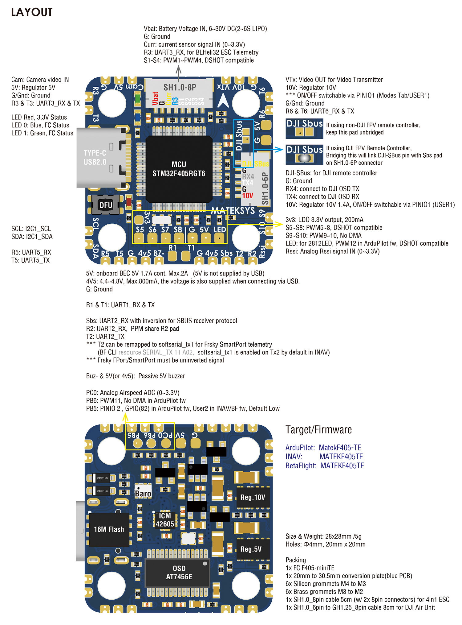
| PWM 5V tolerant I/O |
S1 | PWM1 GPIO50 | TIM8_CH4 | DMA/DShot | Group1 |
| S2 | PWM2 GPIO51 | TIM8_CH3 | DMA/DShot | ||
| S3 | PWM3 GPIO52 | TIM1_CH3N | DMA/DShot | Group2 | |
| S4 | PWM4 GPIO53 | TIM1_CH1 | DMA/DShot | ||
| S5 | PWM5 GPIO54 | TIM2_CH4 | DMA/DShot | Gourp3 | |
| S6 | PWM6 GPIO55 | TIM2_CH3 | DMA/DShot | ||
| S7 | PWM7 GPIO56 | TIM2_CH2 | DMA/DShot | ||
| S8 | PWM8 GPIO57 | TIM2_CH1 | DMA/DShot | ||
| S9 | PWM9 GPIO58 | TIM12_CH1 | NO DMA | Gourp4 | |
| S10 | PWM10 GPIO59 | TIM13_CH1 | NO DMA | Gourp5 | |
| S11 /PB6 pad | PWM11 GPIO60 | TIM4_CH1 | NO DMA | Gourp6 | |
| LED pad | PWM12 GPIO61 | TIM3_CH4 | DMA/DShot | Gourp7 | |
| SERVO12_FUNCTION 120, NTF_LED_TYPES neopixel | |||||
| Mixing Dshot and normal PWM operation for outputs is restricted into groups, ie. enabling Dshot for an output in a group requires that ALL outputs in that group be configured and used as Dshot, rather than PWM outputs. If servo and motor are mixed in same group, make sure this group run lowest PWM frequency according to the servo specification. ie. Servo supports Max. 50Hz, ESC must run at 50Hz in this group. |
|||||
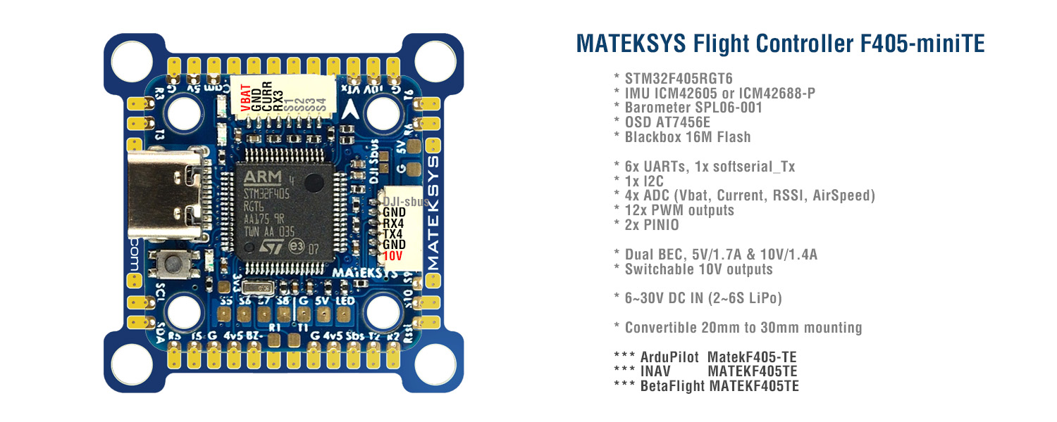
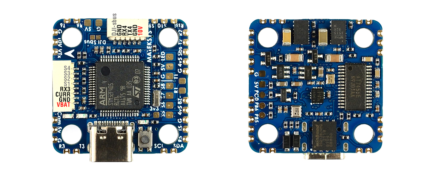
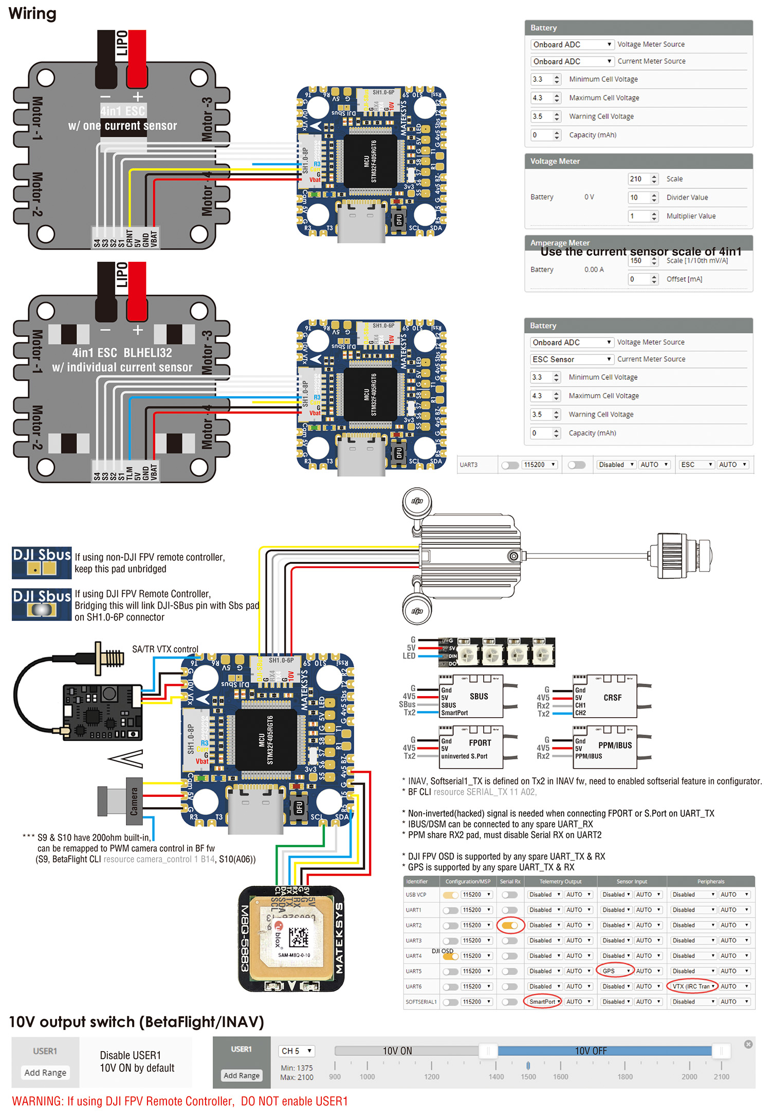
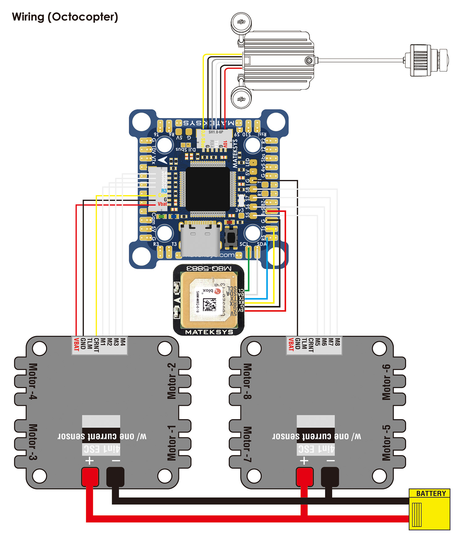
| ADC | Vbat Pad | 1K:20K divider builtin 0~30V |
on board battery voltage | BATT_VOLT_PIN BATT_VOLT_MULT |
14 21.0 |
| Curr pad | 0~3.3V | current sensor ADC | BATT_CURR_PIN BATT_AMP_PERVLT |
15 / |
|
| RSSI Pad | 0~3.3V | RSSI ADC Analog RSSI |
RSSI_ANA_PIN RSSI_TYPE |
8 2 |
|
| AirS /PC0 Pad | no divider builtin 0~3.3V |
AirS ADC Analog Airspeed |
ARSPD_PIN ARSPD_TYPE |
10 2 |
|
| I2C | I2C1 | 5V tolerant I/O | Compass | COMPASS_AUTODEC | 1 |
| onboard Baro SPL06-001 | Address | 0x76 | |||
| Digital Airspeed I2C MS4525 DLVR-L10D |
ARSPD_BUS ARSPD_TYPE ARSPD_TYPE |
1 1 9 |
|||
| UART 5V tolerant I/O |
USB | USB | console | SERIAL0 | |
| TX1 RX1 | USART1 | with DMA | telem1 | SERIAL1 | |
| TX3 RX3 | USART3 | NO DMA | telem2 | SERIAL2 | |
| TX5 RX5 | UART5 | NO DMA | GPS1 | SERIAL3 | |
| TX4 RX4 | UART4 | NO DMA | DJI OSD | SERIAL4 | |
| TX6 RX6 | USART6 | TX6 with DMA | USER | SERIAL5 | |
| TX2 RX2 SBUS |
USART2 | with DMA | RC input/Receiver | SERIAL6 | |
| RX2 | IBUS/DSM/PPM | BRD_ALT_CONFIG 0 Default |
|||
| Sbs pad | SBUS | ||||
| TX2 & RX2 | CRSF | BRD_ALT_CONFIG 1 SERIAL6_PROTOCOL 23 |
SERIAL6_OPTIONS 0 | ||
| TX2 | uninverted FPort (hacked) | SERIAL6_OPTIONS 4 | |||
| TX2 | SRXL2 | SERIAL6_OPTIONS 4 | |||
- If sending highspeed serial data (eg. 921600 baud) to the board, use USART1(Serial1) or USART2(Serial6).
Frsky Smartport Telemetry
- non-inverted (hacked) S.Port signal
- any spare Uart_TX
- SERIALx_BAUD 57
- SERIALx_OPTIONS 7
- SERIALx_PROTOCOL 4 or 10(for yaapu)
DJI FPV OSD (ArduPilot 4.1)
https://ardupilot.org/plane/docs/common-msp-osd-overview.html
- OSD_TYPE = 3
- SERIAL4_PROTOCOL = 33
- MSP_OPTIONS = 0 (polling mode)
Relay(PINIO)
- PINIO_1, 10V On by default
- PINIO_2, PB5 pad, spare
# GPIOs
- PA4 PINIO1 OUTPUT GPIO(81) LOW //10v power switch
- PB5 PINIO2 OUTPUT GPIO(82) LOW //spare
# RCx_OPTION: RC input option
- 28 Relay On/Off
- 34 Relay2 On/Off
- 35 Relay3 On/Off
- 36 Relay4 On/Off
e.g.
- RELAY1_FUNCTION 1
- RELAY_PIN 81 //10V switch PINIO
- RC7_OPTION 28 //Relay On/Off, Use CH7 of Transmitter to control 10V ON/OFF
- RELAY2_FUNCTION 1
- RELAY_PIN2 82 //spare
- RC8_OPTION 34 //Relay2 On/Off, Use CH8 of Transmitter to control high/low level on PB5 pad
The configured feature will be triggered when the auxiliary switch’s pwm value becomes higher than 1800. It will be deactivated when the value falls below 1200.
Check the pwm value sent from the transmitter when the switch is high and low using the Mission Planner’s Initial Setup >> Mandatory Hardware >> Radio Calibration screen. If it does not climb higher than 1800 or lower than 1200, it is best to adjust the servo end points in the transmitter.