PWM
PWM1~PWM13 are Dshot and PWM capable. However, mixing Dshot and normal PWM operation for outputs is restricted into groups, ie. enabling Dshot for an output in a group requires that ALL outputs in that group be configured and used as Dshot, rather than PWM outputs.
If servo and motor are mixed in same group, make sure this group run lowest PWM frequency according to the servo specification. ie. Servo supports Max. 50Hz, ESC must run at 50Hz in this group. |
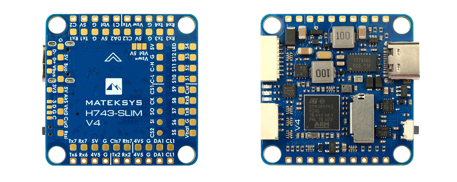
S1 |
PB0 |
5 V tolerant I/O |
PWM1 GPIO50 |
TIM8_CH2N |
Group1 |
| S2 |
PB1 |
3.3 V tolerant I/O |
PWM2 GPIO51 |
TIM8_CH3N |
| S3 |
PA0 |
5 V tolerant I/O |
PWM3 GPIO52 |
TIM5_CH1 |
Group2 |
| S4 |
PA1 |
5 V tolerant I/O |
PWM4 GPIO53 |
TIM5_CH2 |
| S5 |
PA2 |
5 V tolerant I/O |
PWM5 GPIO54 |
TIM5_CH3 |
| S6 |
PA3 |
5 V tolerant I/O |
PWM6 GPIO55 |
TIM5_CH4 |
| S7 |
PD12 |
5 V tolerant I/O |
PWM7 GPIO56 |
TIM4_CH1 |
Gourp3 |
| S8 |
PD13 |
5 V tolerant I/O |
PWM8 GPIO57 |
TIM4_CH2 |
| S9 |
PD14 |
5 V tolerant I/O |
PWM9 GPIO58 |
TIM4_CH3 |
| S10 |
PD15 |
5 V tolerant I/O |
PWM10 GPIO59 |
TIM4_CH4 |
| S11 |
PE5 |
5 V tolerant I/O |
PWM11 GPIO60 |
TIM15_CH1 |
Group4 |
| S12 |
PE6 |
5 V tolerant I/O |
PWM12 GPIO61 |
TIM15_CH2 |
| LED |
PA8 |
5 V tolerant I/O |
PWM13 GPIO62 |
TIM1_CH1 |
Group5 |
| SERVO13_FUNCTION 120, NTF_LED_TYPES neopixel |
|
|
|
|
|
|
|
| ADC |
No pad
1K:10K divider builtin |
PC0 |
0~36V |
on board battery voltage |
BATT_VOLT_PIN
BATT_VOLT_MULT |
10
11.0 |
| No pad |
PC1 |
0~3.3V |
on board current sensor |
BATT_CURR_PIN
BATT_AMP_PERVLT |
11
40 |
Vbat2 Pad
1K:20K divider builtin |
PA4 |
0~69V |
Vbat2 ADC |
BATT2_VOLT_PIN
BATT2_VOLT_MULT |
18
21.0 |
| Cur2 Pad |
PA7 |
0~3.3V |
Cur2 ADC |
BATT2_CURR_PIN
BATT2_AMP_PERVLT |
7
/ |
| RSSI Pad |
PC5 |
0~3.3V |
RSSI ADC
Analog RSSI |
RSSI_ANA_PIN
RSSI_TYPE |
8
1 |
AirS Pad
10K:10K divider builtin |
PC4 |
0~6.6V |
AirS ADC
Analog Airspeed |
ARSPD_PIN
ARSPD_TYPE |
4
2 |
|
|
|
|
|
|
|
| I2C |
I2C1
CL1/DA1 |
PB6/PB7 |
5 V tolerant I/O |
Digital Airspeed I2C |
ARSPD_BUS |
1 |
MS4525
MS5525
DLVR-L10D |
ARSPD_TYPE |
1
3
9 |
| Compass |
COMPASS_AUTODEC |
1 |
| I2C2
CL2/DA2 |
PB10/PB11 |
5 V tolerant I/O |
on board Baro DPS368 |
|
|
|
|
|
|
|
|
|
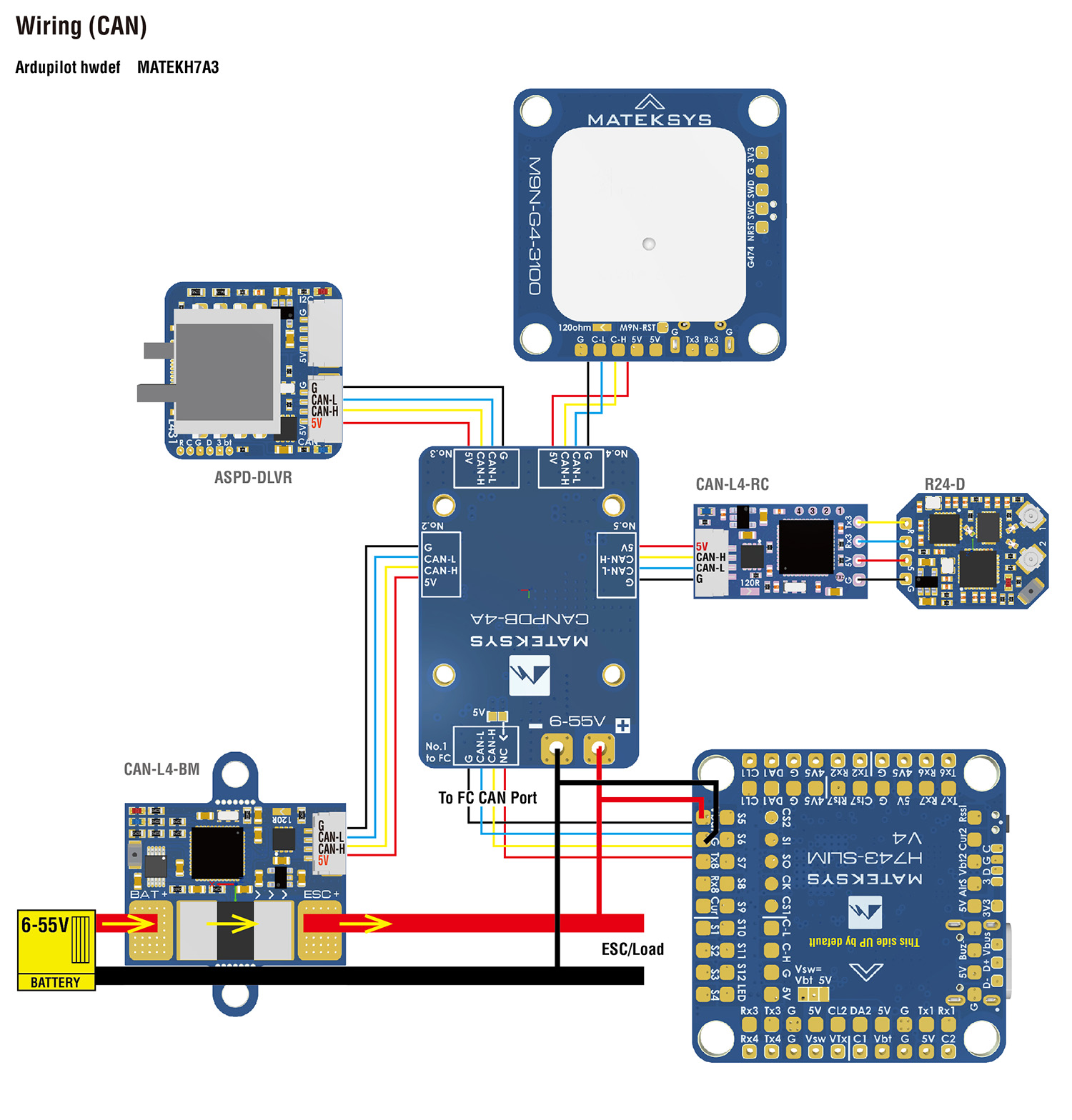
| CAN |
CAN1 |
PD0/PD1 |
5 V tolerant I/O |
F103/F303 CAN Node |
CAN_D1_PROTOCOL
CAN_P1_DRIVER |
1
1 |
| CAN GPS |
GPS_TYPE |
9 |
| CAN Compass |
COMPASS_TYPEMASK |
0 |
| CAN Airspeed sensor |
ARSPD_TYPE |
8 |
|
|
|
|
|
|
|
| UART |
USB |
PA11/PA12 |
5 V tolerant I/O |
USB |
console |
SERIAL0 |
| RX7 TX7 RTS7 CTS7 |
PE7/8/9/10 |
3.3 V tolerant I/O |
UART7 |
telem1 |
SERIAL1 |
| TX1 RX1 |
PA9/PA10 |
5 V tolerant I/O |
USART1 |
telem2 |
SERIAL2 |
| TX2 RX2 |
PD5/PD6 |
5 V tolerant I/O |
USART2 |
GPS1 |
SERIAL3 |
| TX3 RX3 |
PD8/PD9 |
5 V tolerant I/O |
USART3 |
GPS2 |
SERIAL4 |
| TX8 RX8 |
PE1/PE0 |
5 V tolerant I/O |
UART8 |
USER |
SERIAL5 |
| TX4 RX4 |
PB9/PB8 |
5 V tolerant I/O |
UART4 |
USER |
SERIAL6 |
| TX6 RX6 |
PC6/PC7 |
5 V tolerant I/O |
USART6 |
RC input/Receiver |
SERIAL7 |
| RX6 |
SBUS/IBUS/DSM |
|
| RX6 |
PPM |
|
RC INPUT
.
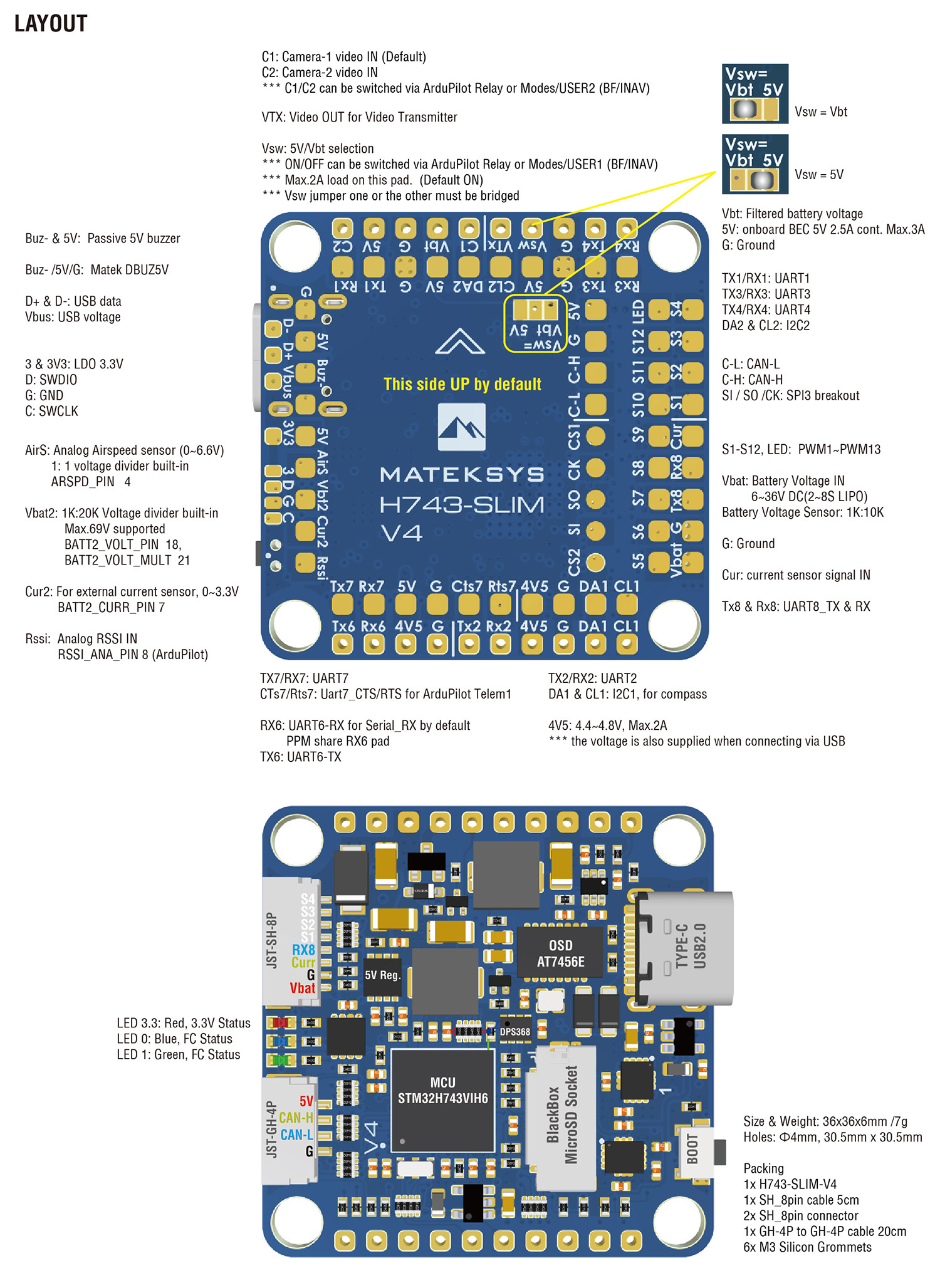
ArduPilot Relay(PINIO)
- Camera-1 and Vsw On by default
- Make sure 2 cameras are set with identical video format, both PAL or both NTSC.
# GPIOs
- PD10 PINIO1 OUTPUT GPIO(81) //Vsw pad power switch
- PD11 PINIO2 OUTPUT GPIO(82) //Camera switch
# RCx_OPTION: RC input option
- 28 Relay1 On/Off
- 34 Relay2 On/Off
- 35 Relay3 On/Off
- 36 Relay4 On/Off
e.g.
- RELAY1_FUNCTION 1
- RELAY1_PIN 81 //Vsw GPIO
- RC7_OPTION 28 //Relay On/Off, Use CH7 of Transmitter to switch Vsw
- RELAY2_FUNCTION 1
- RELAY2_PIN 82 //Camera switch GPIO
- RC8_OPTION 34 //Relay2 On/Off, Use CH8 of Transmitter to switch camera
The configured feature will be triggered when the auxiliary switch’s pwm value becomes higher than 1800. It will be deactivated when the value falls below 1200.
Check the pwm value sent from the transmitter when the switch is high and low using the Mission Planner’s Initial Setup >> Mandatory Hardware >> Radio Calibration screen. If it does not climb higher than 1800 or lower than 1200, it is best to adjust the servo end points in the transmitter.